All numbers are calculated by using these following equations.
\( V_{c} = D \pi S \)
\( V_{f} = f_{z} S Z \)
\( M_{RR} = a_{p} a_{e} V_{f} = a_{p} a_{e} f_{z} S Z \)
\( M_{RR} \):Metal Removal Rate ( = Machining Efficiency)
\( V_{c} \):Cutting speed
\( V_{f} \):Feed speed
\( a_{p} \):Axial depth of cut
\( a_{e} \):Radial depth of cut
\( f_{z} \):Feed per tooth
\( Z \):Number of teeth
\( D \):Cutter Diameter
\( S \):Rotational Speed
Additional Information:
By using above mentioned equations, the following equations are obtained.
\(\displaystyle M_{RR} = \cfrac{ a_{p} a_{e} f_{z} V_{c}}{ \pi } \cfrac{Z}{D} \)
The first term ot this equation consists of cutting conditions.
The second term of this equation consists of Z/D, which shows the density of teeth.
Thus, when you select the extra fine pitch cutter to increase Z with the same cutter diameter, you can increase \(M_{RR} \).
But, you can find another answer.
If you can increase Z/D with small cutter diametar, \(M_{RR} \) is increased.
For example, D:100 mm and Z:10 teeth are equals to D:25 mm and Z:2.5 teeth.
Thus, if you choose D:25mm and Z:3 teeth, you can increase \(M_{RR} \).
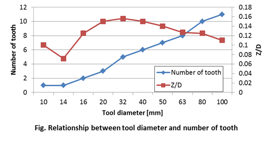
The following figure shows the relationship between the tool diameter and the number of teeth of a milling cutter.
Values in this figure is extracted from a cutting tool catalogue.

In this figure, Z/D has the largest value at tool diameter 32mm.
When you use this relationship, you have to consider that small cutter diameter leads to small stiffness.
And small tool diameter, small number of teeth and high rotational speed causes a short cooling time and a high temperature.
This high temperature decreases a tool life.